Back
How to Test Motor Windings: A Clear Step-by-Step Guide
Learn how to test motor windings effectively with this easy-to-follow guide. Ensure safety and proper functioning of your motor today!
Aug 31, 2025
Aug 31, 2025
Table of Contents
Table of Contents
NOTE: This content is for informational purposes only. EPS Controls assumes no liability for what you do with this information—consult a qualified HVAC technician before making changes.
NOTE: This content is for informational purposes only. EPS Controls assumes no liability for what you do with this information—consult a qualified HVAC technician before making changes.
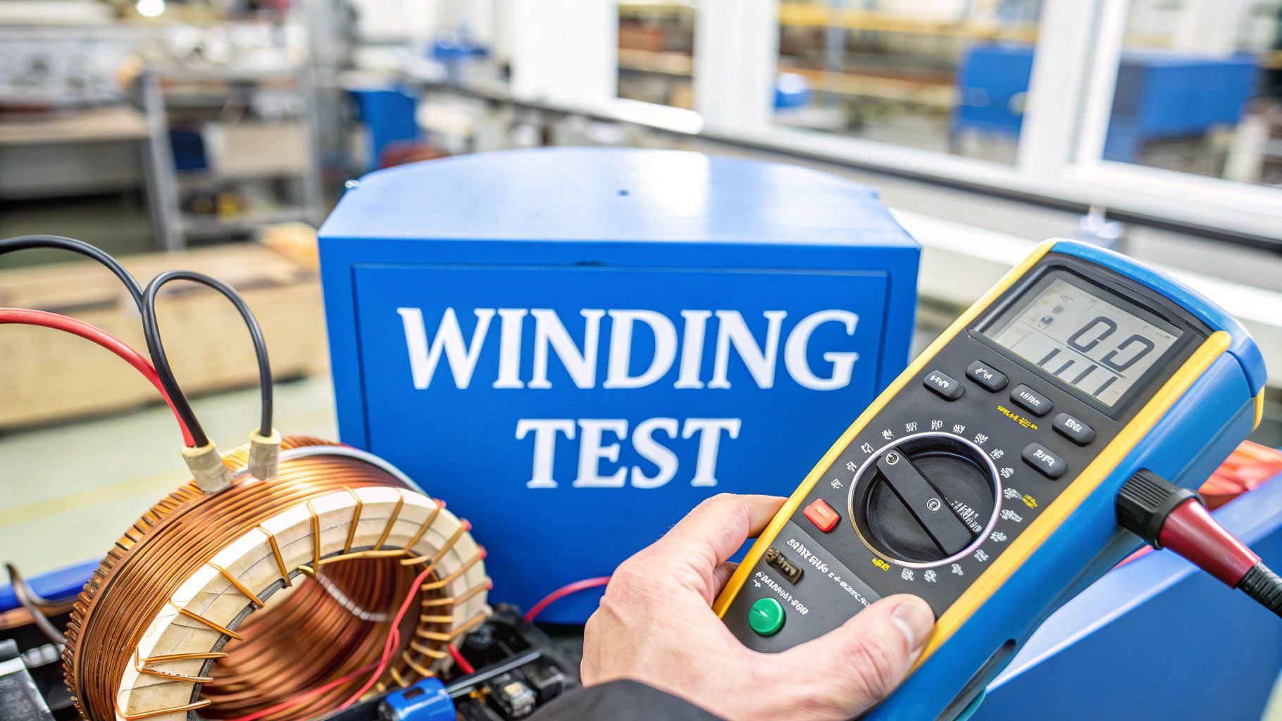
When you're troubleshooting a motor, you're essentially checking its electrical health. This boils down to a few key tests on its windings: a continuity test to make sure the electrical path is complete, a resistance test to see if all windings are balanced, and an insulation resistance test to check for any shorts to the motor's frame. These three checks are your best tools for catching opens, shorts, or insulation decay before a motor completely gives up on you.
Why Bother Testing Motor Windings?

Before you even reach for your meter, let's talk about why this matters. Those copper windings are the soul of the motor; they're what create the magnetic fields that make everything spin. If they fail, the system is dead in the water, and you're looking at frustrating downtime and expensive replacements.
Think of it like checking the oil in your truck. It’s a simple, routine check that prevents a catastrophic engine failure down the line. The same principle applies here.
The insulation protecting these windings is constantly fighting a battle against wear and tear. Several culprits are always at work trying to break it down:
Excessive Heat: This is the big one. Heat is the number one enemy of motor windings, making the insulation brittle until it eventually cracks.
Moisture and Contaminants: A little water, oil, or even conductive dust can create a path for electricity to leak where it shouldn't.
Vibration: The constant rattling and shaking from normal operation can physically wear away the insulation, causing wires to touch each other or the motor frame.
Voltage Spikes: Dirty power or surges can stress and literally puncture the insulation, creating weak points that are just waiting to fail.
Spotting the Early Warning Signs
A motor rarely just dies without warning. It usually gives you some subtle clues first. If you learn to spot them, you can get ahead of the problem.
Keep an ear out for any unusual humming or whining noises. This can be a sign of an imbalance in the magnetic fields, often pointing to a winding issue. Another dead giveaway is a breaker that keeps tripping when the motor starts or is under a heavy load. That’s a classic symptom of the motor pulling too much current, which is frequently caused by an internal short.
Pro Tip: Motors degrade over time; they don't just suddenly break. By learning how to properly test the windings, you can shift from a reactive "fix-it-when-it's-broken" approach to a proactive one, catching issues when they're small and easy to manage.
This guide will walk you through the three core diagnostic tests you need in your toolkit. We'll start with the continuity test, which is a basic pass/fail check to see if the winding is a complete, unbroken circuit. Then we'll move to the resistance test, where we measure the exact resistance of each winding to ensure they match. Finally, the insulation resistance test (often called a "megger test") confirms that the winding insulation is doing its job and not letting voltage leak to the motor's metal case.
Get these three tests down, and you’ll be able to confidently diagnose the vast majority of electrical motor failures you'll encounter in the field.
Essential Tools and Safety Protocols
Before you even think about putting a probe on a motor terminal, let's talk about what really matters: safety. I can't stress this enough. Working around electrical equipment, even when you're sure it's off, is no joke. There are zero shortcuts when it comes to protecting yourself.
Your absolute first step is making sure that motor is completely de-energized. And no, that doesn't just mean flipping a switch. You need to follow a proper Lockout/Tagout (LOTO) procedure every single time. Shut down the power at the breaker or disconnect, slap your personal lock on it so nobody can accidentally power it back up, and attach a tag letting everyone know you're working on the circuit.
Once you've locked it out, you have to prove it's dead. Grab your multimeter, set it to AC voltage, and test every combination: between each power lead, and from each lead to a solid ground. You’re looking for one thing and one thing only: 0 volts. Don’t move on until you see it.
Your Diagnostic Toolkit
Okay, with the motor confirmed dead and locked out, you can get your tools ready. You don’t need a whole truck full of gear for this, just a few key instruments that you can trust. Good, reliable tools aren't just for getting accurate readings; they’re a core part of your safety system.
Here’s the essential gear I keep on hand for testing motor windings:
Digital Multimeter (DMM): This is your go-to for checking continuity and resistance, not to mention verifying that the power is off. For motor windings, you need a quality DMM with a sensitive low-ohms scale to get reliable readings.
Insulation Resistance Tester (Megohmmeter): Most of us just call it a "megger." This is a specialized meter you’ll need for a proper insulation test. It sends a high DC voltage (500V or 1000V, typically) through the windings to find insulation weaknesses that your standard multimeter will completely miss.
Personal Protective Equipment (PPE): This is non-negotiable. At a minimum, you need safety glasses and a good pair of insulated gloves rated for the job. Even with the power off, PPE is your last line of defense against the unexpected.
Pro Tip: Don't try to use a regular multimeter for an insulation resistance test. It just can't do it. A DMM can tell you if there's a dead short to ground, but it doesn't have the high-voltage muscle to properly stress-test the insulation and uncover those subtle, hidden faults that cause intermittent problems.
Having the right tool is one thing; knowing its limitations is another. A cheap multimeter might give you jumpy, unstable readings on a low-ohm winding, fooling you into condemning a perfectly good motor. A small fan motor, for example, might have windings with just a few ohms of resistance—a cheap meter could easily misread that and make them look faulty.
The same goes for the megger. Using the wrong voltage setting can cause more harm than good. Blasting a 230V motor with a 1000V test could potentially damage the insulation you're trying to check. Always, always check the motor's nameplate to figure out the right test voltage before you start. Your tools and your safety procedures are the foundation of every good diagnosis.
How to Perform Winding Resistance Tests
Alright, with the motor completely de-energized and your lockout/tagout in place, it’s time to grab your digital multimeter (DMM). The winding resistance test is one of the most fundamental checks you can do, and it tells you a ton about the electrical health of the motor’s internal coils.
On a typical three-phase motor, you’ll find three main leads, usually labeled T1, T2, and T3. Your mission is to measure the resistance between each pair. Think of it like this: a healthy motor has three identical electrical paths. If the motor is in good shape, the resistance across all three paths should be nearly identical. A big difference between them is a dead giveaway for a problem, like internal damage or a short between the windings that's just waiting to get worse.
Taking the Phase-to-Phase Readings
First things first, set your DMM to the lowest ohms (Ω) setting. A good meter with an auto-ranging feature makes this a breeze. Before you even touch the motor, do a quick sanity check: touch your two meter probes together. The reading should drop to near zero. If it doesn't, you might have bad leads.
Now, you'll measure the resistance between the motor leads in a simple, triangular pattern:
First up: Put one probe on T1 and the other on T2. Jot down that number.
Next: Keep your first probe on T1 and move the second one over to T3. Write that one down, too.
Finally: Measure the last pair by checking between T2 and T3.
The numbers you get should be pretty low, often less than a few ohms for the motors we see in HVAC. But what’s really important is that they're all extremely close to each other—I'm talking within a few percent. For example, a small condenser fan motor might show readings like 1.8 Ω, 1.9 Ω, and 1.8 Ω. That's perfectly fine. A bigger commercial motor could have readings well under 0.5 Ω.
Winding resistance issues are a common culprit in motor failure, accounting for roughly 30% of maintenance calls on industrial motors. High resistance can mean corrosion or heat damage, while a reading that's too low often points to a short. You can get more great insights into motor resistance testing at Tytorobotics.com.
Expert Insight: Don't get too hung up on matching the exact resistance value you might find in a spec sheet. The real story this test tells is in the balance between the readings. Consistency across the three phases is the #1 sign of a healthy set of windings.
Interpreting Winding Resistance Test Results
Here’s a quick reference table to help you make sense of the numbers you're seeing on your meter.
Reading Between Windings (e.g., T1 to T2) | Reading From Winding to Ground | Likely Condition |
|---|---|---|
Balanced and low (e.g., 1.8Ω, 1.9Ω, 1.8Ω) | OL (Open Line) / Infinity | Healthy Motor: Windings are balanced and properly insulated from the frame. |
Unbalanced (e.g., 1.8Ω, 2.9Ω, 1.8Ω) | OL (Open Line) / Infinity | Winding Fault: A significant imbalance points to an internal short or damage. |
Near zero (0Ω) on any pair | OL (Open Line) / Infinity | Shorted Winding: A direct short circuit exists between windings. The motor is bad. |
Balanced and low | Any low resistance reading | Grounded Motor: A dangerous short-to-ground fault exists. The motor must be replaced. |
Basically, you're looking for that sweet spot: balanced readings between the windings and an open line to ground. Anything else warrants a closer look or immediate replacement.
Checking for a Short to Ground
Once you’ve confirmed the phase-to-phase balance, there’s one more critical resistance check you have to do: testing for a short-to-ground. This happens when electricity finds a way to escape the windings and energize the metal frame of the motor—a truly dangerous situation.
This is a dead-simple pass/fail test. Keep your multimeter on the ohms setting. Test from each winding lead to a clean, unpainted spot on the motor's metal casing.
Measure from T1 to the motor frame.
Measure from T2 to the motor frame.
Measure from T3 to the motor frame.
On a healthy motor, your meter should read "OL" (Open Line) or show an infinity symbol every single time. This proves there's no electrical path between the windings and the casing. If you see any resistance reading—no matter how small—you've found a major fault. The motor is grounded and needs to be replaced immediately.
The graphic below shows a more advanced method called a high-potential (Hipot) test, which is used to really stress-test the integrity of the motor's insulation under high voltage.
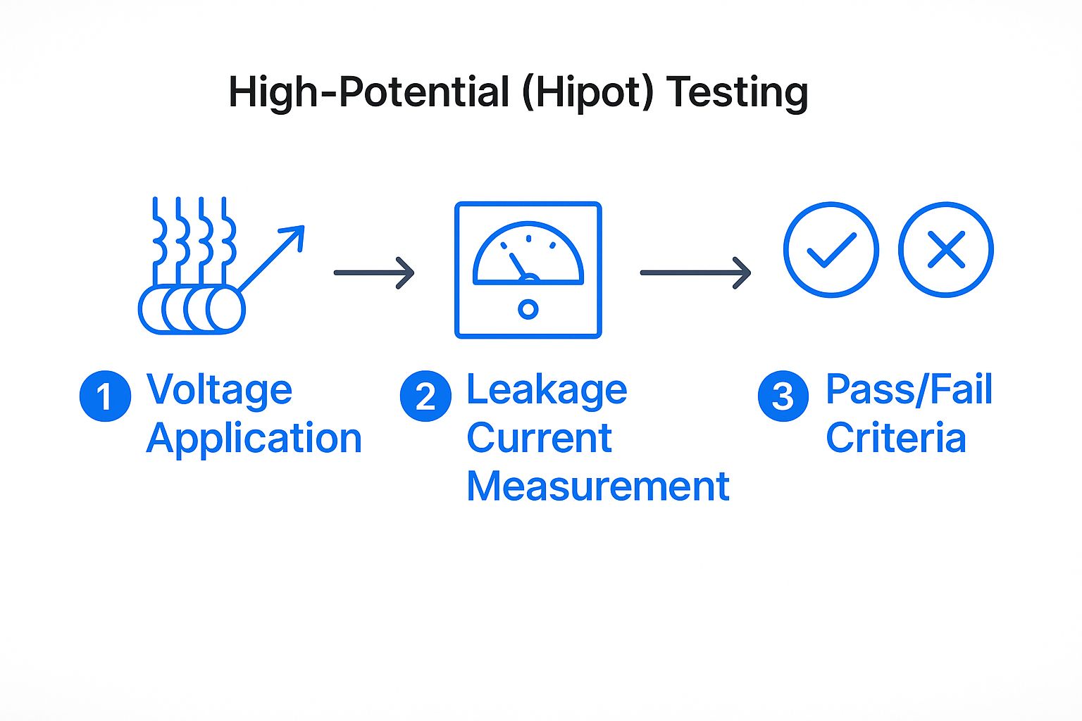
As you can see, the Hipot test applies a much higher voltage than your DMM and measures any tiny current that might leak through the insulation, giving a clear pass/fail result on its ability to handle electrical stress.
Getting to the Truth with an Insulation Resistance Test
Your standard multimeter is great for finding obvious problems like dead shorts or unbalanced windings. But to really know if a motor is on its last legs, you need to go a step further. This is where the insulation resistance test, what we old-timers usually just call a "megger" test, comes into play.
This test is the definitive way to check the integrity of the insulation separating the motor windings from the metal casing. Think of it as a stress test. You're not just looking for a catastrophic failure that's already happened; you're hunting for the hidden weaknesses that lead to those failures down the road.
We do this by sending a high DC voltage through the windings and measuring any current that "leaks" through the insulation to the motor's frame. It's a bit like pressure-testing a refrigerant line—you're intentionally stressing the system to see if it holds.
Choosing the Right Test Voltage
Picking the correct voltage for your megger test is non-negotiable. If you go too low, you won't get a meaningful reading about the insulation's real-world condition. Go too high, and you risk frying the very insulation you're trying to save.
Here’s a solid rule of thumb I’ve always followed:
For any motor rated up to 480V, stick with a 500V DC test setting.
If you're working on something bigger, between 480V and 1000V, you'll want to use the 1000V DC setting.
Before you do anything, always check the motor's nameplate. Blasting a small 230V fan motor with 1000V is a surefire way to let the magic smoke out, and you’ll be the one explaining why it needs replacing.
Running the Test and Making Sense of the Numbers
Alright, with the power still locked out and verified, it’s time to hook up. Connect one lead from your insulation tester (megohmmeter) to all three motor windings tied together. Take your other lead and clamp it onto a clean, unpainted spot on the motor's metal frame.
Now you're set. Press and hold the test button on your meter for a full 60 seconds. You'll probably see the resistance value climb as the test runs—this is normal, as the insulation material becomes polarized. After that one-minute mark, note the final reading in megohms (MΩ).
So, what are you looking for?
Industry standards give us a baseline. The bare minimum acceptable reading is often cited as 1 megohm per kilovolt of the motor's rating, plus an extra 1 megohm. For a standard 480V motor, that works out to about 1.5 MΩ.
But let me be clear: if you see a reading that low, don't just pack up and call it a day. While it might "pass," a number like that is a huge red flag. It’s telling you that the insulation has been compromised, likely by moisture, dirt, or heat damage.
On a new or healthy motor, you should be seeing readings in the hundreds, or even thousands, of megohms. A low reading is your signal to dig deeper, clean and dry the motor, or start budgeting for a replacement before it fails on the hottest day of the year.
For a Deeper Dive: The Polarization Index (PI) Test
If you really want to get a complete picture of the insulation's health, especially if you suspect contamination is the issue, you can run a Polarization Index (PI) test. This is a more advanced diagnostic but provides incredible insight.
It’s a simple concept: you take two readings. The first is your standard 1-minute reading. The second is taken after the test has been running for a full ten minutes. The PI is just the 10-minute reading divided by the 1-minute reading.
Considering that insulation breakdown is the culprit behind roughly 70% of all electric motor failures, this test is an invaluable part of any serious preventive maintenance program. You can learn more about how this key technique improves motor reliability at ReliablePlant.com.
As a general rule, a PI value below 2.0 suggests the insulation is getting old or is contaminated and needs attention soon.
Going Deeper: Advanced Winding Diagnostics

Your multimeter and megohmmeter are the workhorses of motor diagnostics. They’ll catch the majority of common failures. But what about those tricky, intermittent problems or the silent killers that don't show up on a standard test? For those, you need to bring in the heavy hitters.
Think of these advanced diagnostics as an MRI for your motor. They give you a much deeper, more detailed picture of its internal health, revealing subtle weaknesses that simpler tools can't see. This is especially true in industrial settings where an unexpected motor failure can bring an entire production line to a screeching halt.
One of the most powerful tools in this advanced toolkit is surge testing. Frankly, it's the only truly reliable way to find weak turn-to-turn insulation within a single coil. This specific type of fault is a notorious motor killer, creating tiny internal short circuits that are far too subtle for your ohmmeter to ever pick up.
Finding Hidden Killers with Surge Testing
So, how does it work? A surge tester sends a series of controlled, high-voltage pulses through each motor winding, one at a time. It's a non-destructive test that charts the resulting voltage waveform from each phase and then lays them on top of each other.
If the insulation between the individual copper turns inside a coil is compromised, its waveform will look noticeably different from the others. It sticks out like a sore thumb, instantly flagging the bad winding.
This kind of diagnostic is your best bet for catching those turn-to-turn insulation faults that are often the first step toward a complete motor burnout. The test typically starts with a low voltage (around 500V for a 480V motor) and then ramps up. The moment any arcing occurs between the coil turns, you'll see a dramatic shift in the waveform pattern, making even the smallest insulation flaw easy to spot. If you want to dive into the technical standards, you can see how surge testing is standardized by organizations like IEEE at MotorDiagnosticSystems.com.
By finding these subtle weaknesses early, you get to decide when to repair or replace a motor. It puts you back in control, preventing a catastrophic failure and an emergency call-out. It’s the ultimate proactive diagnostic.
Other Powerful Diagnostic Tools
Surge testing is a game-changer, but there are a couple of other high-level tests worth knowing about, especially when dealing with high-voltage or mission-critical motors.
High Potential (Hipot) Testing: Think of this as a stress test for your insulation. A hipot test applies a much higher voltage than a megger to verify that the insulation can handle voltage spikes far beyond its normal operating range. It's a simple pass/fail test.
Partial Discharge Analysis: This is a highly sensitive diagnostic that can actually detect tiny electrical discharges happening inside deteriorating insulation. It's an incredible tool for tracking the long-term health of large, expensive motors over time.
These advanced methods move you beyond just reacting to failures. They allow you to get ahead of them, making them essential for anyone managing systems where reliability isn't just a goal—it's a requirement.
Common Questions About Motor Winding Tests
Even with the right tools and a solid process, a few questions always seem to pop up when you're staring down a motor that isn't behaving. Getting a handle on these common head-scratchers can be the difference between a quick diagnosis and a frustrating callback.
Let's dig into some of the questions I hear most often from techs in the field.
What Is a Good Winding Resistance Reading?
This is the big one, and the honest-to-goodness answer is: it depends. There's no single magic number. A small condenser fan motor might show several ohms across its windings, while a beast of an industrial motor could measure less than a single ohm.
Forget about chasing a specific number you found online or in a manual. The real key is the balance between the windings.
For any three-phase motor, the resistance you measure between T1-T2, T2-T3, and T1-T3 should be incredibly close—practically identical. If you see a difference of more than 5% between any of those readings, you've found your problem. That imbalance is a dead giveaway for an internal fault.
Why Do My Windings Test Good Cold but Fail Under Load?
Ah, the classic mystery. Your meter gives you the all-clear, but the motor trips the breaker as soon as it gets a little work to do. This almost always points to an insulation breakdown that only shows its ugly face when things heat up.
Here’s what’s happening: as the motor runs, the copper windings get hot and expand. If there's a microscopic crack or a weak spot in the enamel insulation between individual turns of wire, that expansion is just enough to press them together and create a short.
Your standard multimeter, and even a megger test on a cold motor, will never see this. That's why a motor can seem perfectly healthy on the bench but die in the field.
This exact scenario is where more advanced tools like surge testers earn their keep. A surge test can spot those subtle turn-to-turn insulation weaknesses that are invisible to standard meters, saving you the headache of swapping out a motor that seems fine.
How Often Should I Be Doing Preventive Motor Testing?
For critical equipment in any commercial or industrial setting, a regular testing schedule is your best friend. It’s the single best way to prevent unplanned downtime. As a baseline, I recommend performing insulation resistance (megger) tests annually.
A simple, effective schedule looks like this:
Annual Check: Perform a full insulation resistance test on all your critical motors once a year.
Keep a Log: Don't just take the reading; write it down! Track the megohm readings for each motor year after year.
Watch for Trends: A slow, steady decline in the readings over time is a clear warning that the insulation is degrading. If a reading suddenly drops off a cliff from one year to the next, it’s time to take action—that motor needs a closer look immediately.
When Should I Repair a Motor Instead of Replacing It?
This decision almost always boils down to simple economics.
For the smaller, standard-frame motors you find in most residential and light commercial HVAC gear, replacement is a no-brainer. The labor bill to have a small motor professionally rewound will almost always be higher than the cost of a brand-new one.
On the other hand, for large, specialized, or very expensive industrial motors, a rewind can be a fantastic value. A reputable motor shop can often bring a motor back to factory specs for a fraction of the cost of a new unit, especially if the frame, shaft, and bearings are in solid shape.
When you're troubleshooting a motor, you're essentially checking its electrical health. This boils down to a few key tests on its windings: a continuity test to make sure the electrical path is complete, a resistance test to see if all windings are balanced, and an insulation resistance test to check for any shorts to the motor's frame. These three checks are your best tools for catching opens, shorts, or insulation decay before a motor completely gives up on you.
Why Bother Testing Motor Windings?
Before you even reach for your meter, let's talk about why this matters. Those copper windings are the soul of the motor; they're what create the magnetic fields that make everything spin. If they fail, the system is dead in the water, and you're looking at frustrating downtime and expensive replacements.
Think of it like checking the oil in your truck. It’s a simple, routine check that prevents a catastrophic engine failure down the line. The same principle applies here.
The insulation protecting these windings is constantly fighting a battle against wear and tear. Several culprits are always at work trying to break it down:
Excessive Heat: This is the big one. Heat is the number one enemy of motor windings, making the insulation brittle until it eventually cracks.
Moisture and Contaminants: A little water, oil, or even conductive dust can create a path for electricity to leak where it shouldn't.
Vibration: The constant rattling and shaking from normal operation can physically wear away the insulation, causing wires to touch each other or the motor frame.
Voltage Spikes: Dirty power or surges can stress and literally puncture the insulation, creating weak points that are just waiting to fail.
Spotting the Early Warning Signs
A motor rarely just dies without warning. It usually gives you some subtle clues first. If you learn to spot them, you can get ahead of the problem.
Keep an ear out for any unusual humming or whining noises. This can be a sign of an imbalance in the magnetic fields, often pointing to a winding issue. Another dead giveaway is a breaker that keeps tripping when the motor starts or is under a heavy load. That’s a classic symptom of the motor pulling too much current, which is frequently caused by an internal short.
Pro Tip: Motors degrade over time; they don't just suddenly break. By learning how to properly test the windings, you can shift from a reactive "fix-it-when-it's-broken" approach to a proactive one, catching issues when they're small and easy to manage.
This guide will walk you through the three core diagnostic tests you need in your toolkit. We'll start with the continuity test, which is a basic pass/fail check to see if the winding is a complete, unbroken circuit. Then we'll move to the resistance test, where we measure the exact resistance of each winding to ensure they match. Finally, the insulation resistance test (often called a "megger test") confirms that the winding insulation is doing its job and not letting voltage leak to the motor's metal case.
Get these three tests down, and you’ll be able to confidently diagnose the vast majority of electrical motor failures you'll encounter in the field.
Essential Tools and Safety Protocols
Before you even think about putting a probe on a motor terminal, let's talk about what really matters: safety. I can't stress this enough. Working around electrical equipment, even when you're sure it's off, is no joke. There are zero shortcuts when it comes to protecting yourself.
Your absolute first step is making sure that motor is completely de-energized. And no, that doesn't just mean flipping a switch. You need to follow a proper Lockout/Tagout (LOTO) procedure every single time. Shut down the power at the breaker or disconnect, slap your personal lock on it so nobody can accidentally power it back up, and attach a tag letting everyone know you're working on the circuit.
Once you've locked it out, you have to prove it's dead. Grab your multimeter, set it to AC voltage, and test every combination: between each power lead, and from each lead to a solid ground. You’re looking for one thing and one thing only: 0 volts. Don’t move on until you see it.
Your Diagnostic Toolkit
Okay, with the motor confirmed dead and locked out, you can get your tools ready. You don’t need a whole truck full of gear for this, just a few key instruments that you can trust. Good, reliable tools aren't just for getting accurate readings; they’re a core part of your safety system.
Here’s the essential gear I keep on hand for testing motor windings:
Digital Multimeter (DMM): This is your go-to for checking continuity and resistance, not to mention verifying that the power is off. For motor windings, you need a quality DMM with a sensitive low-ohms scale to get reliable readings.
Insulation Resistance Tester (Megohmmeter): Most of us just call it a "megger." This is a specialized meter you’ll need for a proper insulation test. It sends a high DC voltage (500V or 1000V, typically) through the windings to find insulation weaknesses that your standard multimeter will completely miss.
Personal Protective Equipment (PPE): This is non-negotiable. At a minimum, you need safety glasses and a good pair of insulated gloves rated for the job. Even with the power off, PPE is your last line of defense against the unexpected.
Pro Tip: Don't try to use a regular multimeter for an insulation resistance test. It just can't do it. A DMM can tell you if there's a dead short to ground, but it doesn't have the high-voltage muscle to properly stress-test the insulation and uncover those subtle, hidden faults that cause intermittent problems.
Having the right tool is one thing; knowing its limitations is another. A cheap multimeter might give you jumpy, unstable readings on a low-ohm winding, fooling you into condemning a perfectly good motor. A small fan motor, for example, might have windings with just a few ohms of resistance—a cheap meter could easily misread that and make them look faulty.
The same goes for the megger. Using the wrong voltage setting can cause more harm than good. Blasting a 230V motor with a 1000V test could potentially damage the insulation you're trying to check. Always, always check the motor's nameplate to figure out the right test voltage before you start. Your tools and your safety procedures are the foundation of every good diagnosis.
How to Perform Winding Resistance Tests
Alright, with the motor completely de-energized and your lockout/tagout in place, it’s time to grab your digital multimeter (DMM). The winding resistance test is one of the most fundamental checks you can do, and it tells you a ton about the electrical health of the motor’s internal coils.
On a typical three-phase motor, you’ll find three main leads, usually labeled T1, T2, and T3. Your mission is to measure the resistance between each pair. Think of it like this: a healthy motor has three identical electrical paths. If the motor is in good shape, the resistance across all three paths should be nearly identical. A big difference between them is a dead giveaway for a problem, like internal damage or a short between the windings that's just waiting to get worse.
Taking the Phase-to-Phase Readings
First things first, set your DMM to the lowest ohms (Ω) setting. A good meter with an auto-ranging feature makes this a breeze. Before you even touch the motor, do a quick sanity check: touch your two meter probes together. The reading should drop to near zero. If it doesn't, you might have bad leads.
Now, you'll measure the resistance between the motor leads in a simple, triangular pattern:
First up: Put one probe on T1 and the other on T2. Jot down that number.
Next: Keep your first probe on T1 and move the second one over to T3. Write that one down, too.
Finally: Measure the last pair by checking between T2 and T3.
The numbers you get should be pretty low, often less than a few ohms for the motors we see in HVAC. But what’s really important is that they're all extremely close to each other—I'm talking within a few percent. For example, a small condenser fan motor might show readings like 1.8 Ω, 1.9 Ω, and 1.8 Ω. That's perfectly fine. A bigger commercial motor could have readings well under 0.5 Ω.
Winding resistance issues are a common culprit in motor failure, accounting for roughly 30% of maintenance calls on industrial motors. High resistance can mean corrosion or heat damage, while a reading that's too low often points to a short. You can get more great insights into motor resistance testing at Tytorobotics.com.
Expert Insight: Don't get too hung up on matching the exact resistance value you might find in a spec sheet. The real story this test tells is in the balance between the readings. Consistency across the three phases is the #1 sign of a healthy set of windings.
Interpreting Winding Resistance Test Results
Here’s a quick reference table to help you make sense of the numbers you're seeing on your meter.
Reading Between Windings (e.g., T1 to T2) | Reading From Winding to Ground | Likely Condition |
|---|---|---|
Balanced and low (e.g., 1.8Ω, 1.9Ω, 1.8Ω) | OL (Open Line) / Infinity | Healthy Motor: Windings are balanced and properly insulated from the frame. |
Unbalanced (e.g., 1.8Ω, 2.9Ω, 1.8Ω) | OL (Open Line) / Infinity | Winding Fault: A significant imbalance points to an internal short or damage. |
Near zero (0Ω) on any pair | OL (Open Line) / Infinity | Shorted Winding: A direct short circuit exists between windings. The motor is bad. |
Balanced and low | Any low resistance reading | Grounded Motor: A dangerous short-to-ground fault exists. The motor must be replaced. |
Basically, you're looking for that sweet spot: balanced readings between the windings and an open line to ground. Anything else warrants a closer look or immediate replacement.
Checking for a Short to Ground
Once you’ve confirmed the phase-to-phase balance, there’s one more critical resistance check you have to do: testing for a short-to-ground. This happens when electricity finds a way to escape the windings and energize the metal frame of the motor—a truly dangerous situation.
This is a dead-simple pass/fail test. Keep your multimeter on the ohms setting. Test from each winding lead to a clean, unpainted spot on the motor's metal casing.
Measure from T1 to the motor frame.
Measure from T2 to the motor frame.
Measure from T3 to the motor frame.
On a healthy motor, your meter should read "OL" (Open Line) or show an infinity symbol every single time. This proves there's no electrical path between the windings and the casing. If you see any resistance reading—no matter how small—you've found a major fault. The motor is grounded and needs to be replaced immediately.
The graphic below shows a more advanced method called a high-potential (Hipot) test, which is used to really stress-test the integrity of the motor's insulation under high voltage.
As you can see, the Hipot test applies a much higher voltage than your DMM and measures any tiny current that might leak through the insulation, giving a clear pass/fail result on its ability to handle electrical stress.
Getting to the Truth with an Insulation Resistance Test
Your standard multimeter is great for finding obvious problems like dead shorts or unbalanced windings. But to really know if a motor is on its last legs, you need to go a step further. This is where the insulation resistance test, what we old-timers usually just call a "megger" test, comes into play.
This test is the definitive way to check the integrity of the insulation separating the motor windings from the metal casing. Think of it as a stress test. You're not just looking for a catastrophic failure that's already happened; you're hunting for the hidden weaknesses that lead to those failures down the road.
We do this by sending a high DC voltage through the windings and measuring any current that "leaks" through the insulation to the motor's frame. It's a bit like pressure-testing a refrigerant line—you're intentionally stressing the system to see if it holds.
Choosing the Right Test Voltage
Picking the correct voltage for your megger test is non-negotiable. If you go too low, you won't get a meaningful reading about the insulation's real-world condition. Go too high, and you risk frying the very insulation you're trying to save.
Here’s a solid rule of thumb I’ve always followed:
For any motor rated up to 480V, stick with a 500V DC test setting.
If you're working on something bigger, between 480V and 1000V, you'll want to use the 1000V DC setting.
Before you do anything, always check the motor's nameplate. Blasting a small 230V fan motor with 1000V is a surefire way to let the magic smoke out, and you’ll be the one explaining why it needs replacing.
Running the Test and Making Sense of the Numbers
Alright, with the power still locked out and verified, it’s time to hook up. Connect one lead from your insulation tester (megohmmeter) to all three motor windings tied together. Take your other lead and clamp it onto a clean, unpainted spot on the motor's metal frame.
Now you're set. Press and hold the test button on your meter for a full 60 seconds. You'll probably see the resistance value climb as the test runs—this is normal, as the insulation material becomes polarized. After that one-minute mark, note the final reading in megohms (MΩ).
So, what are you looking for?
Industry standards give us a baseline. The bare minimum acceptable reading is often cited as 1 megohm per kilovolt of the motor's rating, plus an extra 1 megohm. For a standard 480V motor, that works out to about 1.5 MΩ.
But let me be clear: if you see a reading that low, don't just pack up and call it a day. While it might "pass," a number like that is a huge red flag. It’s telling you that the insulation has been compromised, likely by moisture, dirt, or heat damage.
On a new or healthy motor, you should be seeing readings in the hundreds, or even thousands, of megohms. A low reading is your signal to dig deeper, clean and dry the motor, or start budgeting for a replacement before it fails on the hottest day of the year.
For a Deeper Dive: The Polarization Index (PI) Test
If you really want to get a complete picture of the insulation's health, especially if you suspect contamination is the issue, you can run a Polarization Index (PI) test. This is a more advanced diagnostic but provides incredible insight.
It’s a simple concept: you take two readings. The first is your standard 1-minute reading. The second is taken after the test has been running for a full ten minutes. The PI is just the 10-minute reading divided by the 1-minute reading.
Considering that insulation breakdown is the culprit behind roughly 70% of all electric motor failures, this test is an invaluable part of any serious preventive maintenance program. You can learn more about how this key technique improves motor reliability at ReliablePlant.com.
As a general rule, a PI value below 2.0 suggests the insulation is getting old or is contaminated and needs attention soon.
Going Deeper: Advanced Winding Diagnostics
Your multimeter and megohmmeter are the workhorses of motor diagnostics. They’ll catch the majority of common failures. But what about those tricky, intermittent problems or the silent killers that don't show up on a standard test? For those, you need to bring in the heavy hitters.
Think of these advanced diagnostics as an MRI for your motor. They give you a much deeper, more detailed picture of its internal health, revealing subtle weaknesses that simpler tools can't see. This is especially true in industrial settings where an unexpected motor failure can bring an entire production line to a screeching halt.
One of the most powerful tools in this advanced toolkit is surge testing. Frankly, it's the only truly reliable way to find weak turn-to-turn insulation within a single coil. This specific type of fault is a notorious motor killer, creating tiny internal short circuits that are far too subtle for your ohmmeter to ever pick up.
Finding Hidden Killers with Surge Testing
So, how does it work? A surge tester sends a series of controlled, high-voltage pulses through each motor winding, one at a time. It's a non-destructive test that charts the resulting voltage waveform from each phase and then lays them on top of each other.
If the insulation between the individual copper turns inside a coil is compromised, its waveform will look noticeably different from the others. It sticks out like a sore thumb, instantly flagging the bad winding.
This kind of diagnostic is your best bet for catching those turn-to-turn insulation faults that are often the first step toward a complete motor burnout. The test typically starts with a low voltage (around 500V for a 480V motor) and then ramps up. The moment any arcing occurs between the coil turns, you'll see a dramatic shift in the waveform pattern, making even the smallest insulation flaw easy to spot. If you want to dive into the technical standards, you can see how surge testing is standardized by organizations like IEEE at MotorDiagnosticSystems.com.
By finding these subtle weaknesses early, you get to decide when to repair or replace a motor. It puts you back in control, preventing a catastrophic failure and an emergency call-out. It’s the ultimate proactive diagnostic.
Other Powerful Diagnostic Tools
Surge testing is a game-changer, but there are a couple of other high-level tests worth knowing about, especially when dealing with high-voltage or mission-critical motors.
High Potential (Hipot) Testing: Think of this as a stress test for your insulation. A hipot test applies a much higher voltage than a megger to verify that the insulation can handle voltage spikes far beyond its normal operating range. It's a simple pass/fail test.
Partial Discharge Analysis: This is a highly sensitive diagnostic that can actually detect tiny electrical discharges happening inside deteriorating insulation. It's an incredible tool for tracking the long-term health of large, expensive motors over time.
These advanced methods move you beyond just reacting to failures. They allow you to get ahead of them, making them essential for anyone managing systems where reliability isn't just a goal—it's a requirement.
Common Questions About Motor Winding Tests
Even with the right tools and a solid process, a few questions always seem to pop up when you're staring down a motor that isn't behaving. Getting a handle on these common head-scratchers can be the difference between a quick diagnosis and a frustrating callback.
Let's dig into some of the questions I hear most often from techs in the field.
What Is a Good Winding Resistance Reading?
This is the big one, and the honest-to-goodness answer is: it depends. There's no single magic number. A small condenser fan motor might show several ohms across its windings, while a beast of an industrial motor could measure less than a single ohm.
Forget about chasing a specific number you found online or in a manual. The real key is the balance between the windings.
For any three-phase motor, the resistance you measure between T1-T2, T2-T3, and T1-T3 should be incredibly close—practically identical. If you see a difference of more than 5% between any of those readings, you've found your problem. That imbalance is a dead giveaway for an internal fault.
Why Do My Windings Test Good Cold but Fail Under Load?
Ah, the classic mystery. Your meter gives you the all-clear, but the motor trips the breaker as soon as it gets a little work to do. This almost always points to an insulation breakdown that only shows its ugly face when things heat up.
Here’s what’s happening: as the motor runs, the copper windings get hot and expand. If there's a microscopic crack or a weak spot in the enamel insulation between individual turns of wire, that expansion is just enough to press them together and create a short.
Your standard multimeter, and even a megger test on a cold motor, will never see this. That's why a motor can seem perfectly healthy on the bench but die in the field.
This exact scenario is where more advanced tools like surge testers earn their keep. A surge test can spot those subtle turn-to-turn insulation weaknesses that are invisible to standard meters, saving you the headache of swapping out a motor that seems fine.
How Often Should I Be Doing Preventive Motor Testing?
For critical equipment in any commercial or industrial setting, a regular testing schedule is your best friend. It’s the single best way to prevent unplanned downtime. As a baseline, I recommend performing insulation resistance (megger) tests annually.
A simple, effective schedule looks like this:
Annual Check: Perform a full insulation resistance test on all your critical motors once a year.
Keep a Log: Don't just take the reading; write it down! Track the megohm readings for each motor year after year.
Watch for Trends: A slow, steady decline in the readings over time is a clear warning that the insulation is degrading. If a reading suddenly drops off a cliff from one year to the next, it’s time to take action—that motor needs a closer look immediately.
When Should I Repair a Motor Instead of Replacing It?
This decision almost always boils down to simple economics.
For the smaller, standard-frame motors you find in most residential and light commercial HVAC gear, replacement is a no-brainer. The labor bill to have a small motor professionally rewound will almost always be higher than the cost of a brand-new one.
On the other hand, for large, specialized, or very expensive industrial motors, a rewind can be a fantastic value. A reputable motor shop can often bring a motor back to factory specs for a fraction of the cost of a new unit, especially if the frame, shaft, and bearings are in solid shape.
Keep Reading
Related Articles

What is a VFD in HVAC? A Practical Explainer
What is a VFD in HVAC? A Practical Explainer
What is a VFD in HVAC? Learn how Variable Frequency Drives work, their key benefits for energy savings, and their most common applications in modern buildings.
Aug 7, 2025
Aug 7, 2025

Your Guide to Refrigerant Pressure Temp Charts
Your Guide to Refrigerant Pressure Temp Charts
Master the refrigerant pressure temp chart. This guide explains how to read and use PT charts for system diagnosis, charging, and ensuring HVAC efficiency.
Aug 8, 2025
Aug 8, 2025

How to Read HVAC Wiring Diagrams: A Complete Guide
How to Read HVAC Wiring Diagrams: A Complete Guide
Learn how to read HVAC wiring diagrams with our easy-to-follow guide. Master wiring diagrams quickly and confidently.
Aug 8, 2025
Aug 8, 2025
What is a VFD in HVAC? A Practical Explainer
What is a VFD in HVAC? Learn how Variable Frequency Drives work, their key benefits for energy savings, and their most common applications in modern buildings.
Aug 7, 2025
Aug 7, 2025
Your Guide to Refrigerant Pressure Temp Charts
Master the refrigerant pressure temp chart. This guide explains how to read and use PT charts for system diagnosis, charging, and ensuring HVAC efficiency.
Aug 8, 2025
Aug 8, 2025
How to Read HVAC Wiring Diagrams: A Complete Guide
Learn how to read HVAC wiring diagrams with our easy-to-follow guide. Master wiring diagrams quickly and confidently.
Aug 8, 2025
Aug 8, 2025

How to Read a Refractometer for Perfect Results
Learn how to read a refractometer with our expert guide. Get clear, actionable steps for accurate readings and master this essential skill today.
Aug 10, 2025
Aug 10, 2025

Condenser Fan Motors


Pressure Transducers


Sensors

EBUS Horizontal Outside Air Temp/RH Sensor
Aftermarket Part for AAON ASM01836

EBUS Vertical Outside Air Temp/RH Sensor
Aftermarket Part for AAON ASM01838

Duct Mount Humidity/Temp Sensor
Aftermarket Part for Addison 0843P-0586
Duct Euro Humidity/Temperature Sensor
Aftermarket Part for Addison

Outdoor Humidity/Temperature Sensor
Aftermarket Part for Addison 0843P-0587

Room Humidity/Temperature Sensor
Aftermarket Part for Addison

Outdoor Euro Temperature Sensor
Aftermarket Part for Addison

Suction Line Temperature Sensor
Aftermarket Part for Addison 0843P-0838
Variable Frequency Drives

Microchannel Coils

Circuit Breakers


Refrigeration Parts
Soon
0-250psi
Aftermarket Part for Addison 0515P-0783
0-250psi
Aftermarket Part for Addison 0515P-0783
0-250psi
Aftermarket Part for Addison 0515P-0783
0-250psi
Aftermarket Part for Addison 0515P-0783
0-250psi
Aftermarket Part for Addison 0515P-0783
0-250psi
Aftermarket Part for Addison 0515P-0783
0-250psi
Aftermarket Part for Addison 0515P-0783
0-250psi
Aftermarket Part for Addison 0515P-0783
Condenser Fan Motors
Pressure Transducers
Sensors
EBUS Horizontal Outside Air Temp/RH Sensor
Aftermarket Part for AAON ASM01836
EBUS Vertical Outside Air Temp/RH Sensor
Aftermarket Part for AAON ASM01838
Duct Mount Humidity/Temp Sensor
Aftermarket Part for Addison 0843P-0586
Duct Euro Humidity/Temperature Sensor
Aftermarket Part for Addison
Outdoor Humidity/Temperature Sensor
Aftermarket Part for Addison 0843P-0587
Room Humidity/Temperature Sensor
Aftermarket Part for Addison
Outdoor Euro Temperature Sensor
Aftermarket Part for Addison
Suction Line Temperature Sensor
Aftermarket Part for Addison 0843P-0838
Variable Frequency Drives
Microchannel Coils
Circuit Breakers
Refrigeration Parts
Soon
0-250psi
Aftermarket Part for Addison 0515P-0783
0-250psi
Aftermarket Part for Addison 0515P-0783
0-250psi
Aftermarket Part for Addison 0515P-0783
0-250psi
Aftermarket Part for Addison 0515P-0783
0-250psi
Aftermarket Part for Addison 0515P-0783
0-250psi
Aftermarket Part for Addison 0515P-0783
0-250psi
Aftermarket Part for Addison 0515P-0783
0-250psi
Aftermarket Part for Addison 0515P-0783